RC Time Constant: How Capacitance and Resistance Define Circuit Response
It is often said that timing is everything, and this is certainly no less the case in the world of electronics. Whether you’re designing a simple timer for a household gadget, or perhaps fine-tuning a filter in an audio amplifier, it will be crucial for you to understand how circuits respond to changes. At the centre of many such designs, is the RC time constant.
In this article, then, we will explore what the RC time constant is, and the importance of the interplay between resistance (R) and capacitance (C) when it comes to putting together efficient and reliable systems.
An Introduction to RC Circuits
In the grand sphere of electronics, setups don’t come much simpler or more versatile than the RC circuit. This kind of circuit entails a resistor being combined with a capacitor – the former component opposing the flow of current, and the latter storing electrical charge.
It is possible to have these components wired in series or in parallel. As far as timing applications are concerned, though, the classic configuration is a series RC network connected to a voltage source.
In summary:
- Resistors slow down current, and are measured in ohms (Ω).
- Capacitors act like tiny rechargeable batteries, storing energy in an electric field. They are measured in farads (F), although for practical purposes, it is often such subunits as microfarads (µF) and picofarads (pF) that are used.
The application of a voltage causes the capacitor to begin charging through the resistor. Conversely, the removal of the voltage results in its discharge.
However, the rate at which this charging or discharging occurs is not instantaneous. That’s because it is dictated by the RC time constant, denoted as τ.
Understanding The RC Time Constant
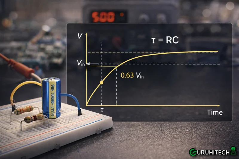
The time constant is mathematically defined as the product of the resistance and the capacitance. It can be expressed, then, as the elegantly simple τ = R x C, where R is in ohms (Ω), C is in farads (F), and τ is in seconds (s).
The single value that results from this calculation therefore, encapsulates the circuit’s “memory” or response speed:
- If τ is large due to high R or high C, this equates to a sluggish response, with the capacitor taking longer to fill or empty.
- If τ is small due to low R or low C, this means a quick reaction can be expected.
Physically, τ represents the time it takes for the capacitor’s voltage to reach approximately 63.2% of its final value during charging, or to drop to 36.8% during discharging.
How, Then, Do Capacitance and Resistance Shape Circuit Response?
The sheer “tunability” of the RC time constant is a significant boon for engineers, hobbyists, and students alike. You can simply tweak R or C to directly control the temporal behaviour of the circuit, thereby also defining its overall response:
- Charging And Discharging Dynamics
Picture something as simple as flicking a switch to power an LED through an RC network. The resistor limits the initial surge, so that the capacitor can charge gradually.
The time constant determines the “fade-in” effect. If it is too small, the LED will snap on, but in the event of it being too large, it will dim slowly, akin to a theatre light.
In discharging mode, such as in a timing circuit, the capacitor will release stored energy at a rate set by τ, powering the load until it is depleted.
- Frequency Response in Filters
RC circuits form the backbone of high-pass and low-pass filters. The cutoff frequency, the point at which the signal’s power is cut in half, can be expressed as fc = 1/(2πτ).
When τ is larger, the cutoff will be shifted lower, thereby filtering out high frequencies (for example, reducing noise in a power supply).
This is imperative in UK-regulated audio equipment, for instance, where signal integrity must adhere to stringent Electromagnetic Compatibility (EMC) standards.
- Timing And Delay Applications
The time constant introduces controlled delays. This can be greatly useful for applications ranging from debounce circuits in keyboards to RC snubbers protecting relays from voltage spikes.
When it comes to microcontroller projects, which many makers engage in using platforms like Raspberry Pi, RC delays can prevent false triggers or synchronise events.
In the absence of proper τ calculation, circuits can be vulnerable to oscillating, overheating, or failing prematurely.
Just One More Thing About Time Constant Calculations…
As a final note, it is worth being aware that you can determine delay with the RC time constant calculator for electronic circuits on the website of RS, the trusted electrical component supplier. Of course, many similar online tools are also available.
In electronic design, predicting delay is essential, rather than a mere optional extra or “nice to do”. If efforts aren’t made to calculate τ, this can lead to timing mismatches or excessive power draw from prolonged charging. So, online calculators like these can be instrumental in verifying the accuracy of manual calculations and speeding up the design process.
Ti potrebbe interessare:
Segui guruhitech su:
- Google News: bit.ly/gurugooglenews
- Telegram: t.me/guruhitech
- X (Twitter): x.com/guruhitech1
- Bluesky: bsky.app/profile/guruhitech.bsky.social
- GETTR: gettr.com/user/guruhitech
- Rumble: rumble.com/user/guruhitech
- VKontakte: vk.com/guruhitech
- MeWe: mewe.com/i/guruhitech
- Skype: live:.cid.d4cf3836b772da8a
- WhatsApp: bit.ly/whatsappguruhitech
Esprimi il tuo parere!
Ti è stato utile questo articolo? Lascia un commento nell’apposita sezione che trovi più in basso e se ti va, iscriviti alla newsletter.
Per qualsiasi domanda, informazione o assistenza nel mondo della tecnologia, puoi inviare una email all’indirizzo [email protected].
Scopri di più da GuruHiTech
Abbonati per ricevere gli ultimi articoli inviati alla tua e-mail.